OXYGEN/AIR FUEL SENSORS
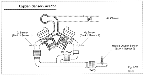
Oxygen and Air/Fuel Ratio Sensors The ECM uses an oxygen sensor to ensure the air/fuel ratio is correct for the catalytic converter. Based on the oxygen sensor signal, the ECM will adjust the amount of fuel injected into the intake air stream.
There are different types of oxygen sensors, but two of the more common types are:
• the narrow range oxygen sensor, the oldest style, simply called the oxygen sensor.
• wide range oxygen sensor, the newest style, called the air/fuel ratio (A/F) sensor.
Also used on very limited models in the early 90s, was the Titania oxygen sensor.
OBD II vehicles require two oxygen sensors: one before and one after the catalytic converter. The oxygen sensor, or air/fuel ratio sensor, before the catalytic converter is used by the ECM to adjust the air/fuel ratio. This sensor in OBD II terms is referred to as sensor 1. On V-type engines one sensor will be referred to as Bank I Sensor 1 and the other as Bank 2 Sensor 1. The oxygen sensor after the catalytic converter is used by the ECM primarily to determine catalytic converter efficiency. This sensor is refer-red to as sensor 2. With two catalytic converters, one sensor will be Bank 1 Sensor 2 and the other as Bank 2 Sensor 2.
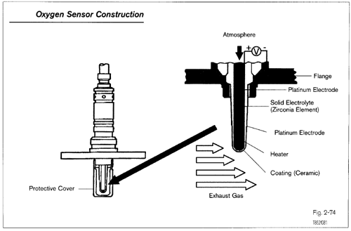
Oxygen Sensor This style of oxygen sensor has been in service the longest time. It is made of zirconia (zirconium dioxide), platinum electrodes, and a heater. The oxygen sensor generates a voltage signal based on the amount of oxygen in the exhaust compared to the atmospheric oxygen. The zirconia element has one side exposed to the exhaust stream, the other side open to the atmosphere. Each side has a platinum electrode attached to Zirconium dioxide element.
The platinum electrodes conduct the voltage generated. Contamination or corrosion of the platinum electrodes or zirconia elements will reduce the voltage signal output.
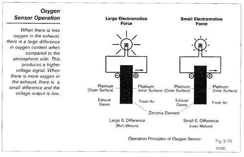
Operation When exhaust oxygen content is high, oxygen sensor voltage output is low. When exhaust oxygen content is low, oxygen sensor voltage output is high. The greater the difference in oxygen content between the exhaust stream and atmosphere, the higher the voltage signal.

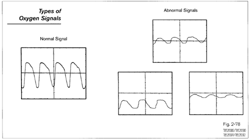
From the oxygen content, the ECM can determine if the air/fuel ratio is rich or lean and adjusts the fuel mixture accordingly. A rich mixture consumes nearly all the oxygen, so the voltage signal is high, in the range of 0.6 - 1.0 volts. A lean mixture has more available oxygen after combustion than a rich mixture, so the voltage signal is low, 0.4 - 0.1 volts. At the stoichiometric air/fuel ratio (14.7: 1), oxygen sensor voltage output is approximately 0.45 volts.
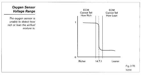
Small changes in the air/fuel ratio from the stoichiometric point radically changes the voltage signal. This type of oxygen sensor is sometimes referred to as a narrow range sensor because it cannot detect the small changes in the exhaust stream oxygen content produced by changes in the air/fuel mixture. The ECM will continuously add and subtract fuel producing a rich/lean cycle. Refer to Closed Loop Fuel Control in the Fuel Injection section for more information.
NOTE: Think of the oxygen sensor as a switch. Each time the air/fuel ratio is at stoichiometry (14.7: 1) the oxygen sensor switches either high or low.
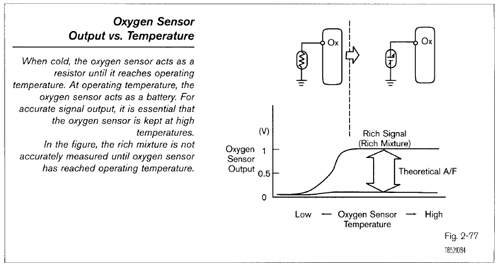
The oxygen sensor will only generate an accurate signal when it has reached a minimum operating temperature of 400'C (7500F). To quickly warm up the oxygen sensor and to keep it hot at idle and light load conditions, the oxygen sensor has a heater built into it. This heater is controlled by the ECM. See Oxygen Sensor Heater Control for more information.
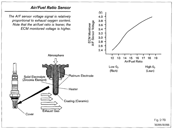
Air/Fuel Ratio Sensor The Air/Fuel Ratio (A/F) sensor is similar to the narrow range oxygen sensor. Though it appears similar to the oxygen sensor, it is constructed differently and has different operating characteristics. The A/F sensor is also referred to as a wide range or wide ratio sensor because of its ability to detect air/fuel ratios over a wide range. The advantage of using the A/F sensor is that the ECM can more accurately meter the fuel reducing emissions. To accomplish this, the A/F sensor:
• operates at approximately 650'C (1200'F), much hotter than the oxygen sensor 400'C (750'F).
• changes its current (amperage) output in relation to the amount of oxygen in the exhaust stream.
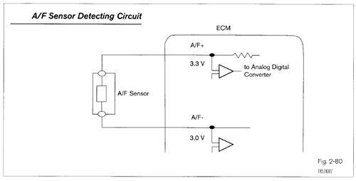
Operation A detection circuit in the ECM detects the change and strength of current flow and puts out a voltage signal relatively proportional to exhaust oxygen content.
NOTE: This voltage signal can only be measured by using the Diagnostic Tester or OBD II compatible scan tool. The A/F sensor current output cannot be accurately measured directly. If an OBD 11 scan tool is used, refer to the Repair Manual for conversion, for the output signal is different.
The A/F sensor is designed so that at stoichiometry, there is no current flow and the voltage put out by the detection circuit is 3.3 volts. A rich mixture, which leaves very little oxygen in the exhaust stream, produces a negative current flow. The detection circuit will produce a voltage below 3.3 volts. A lean mixture, which has more oxygen in the exhaust stream, produces a positive current flow. The detection circuit will now produce a voltage signal above 3.3 volts.

NOTE
The A/F sensor voltage output is the opposite of what happens in the narrow range oxygen sensor. Voltage output through the detection circuit increases as the mixture gets leaner. Also, the voltage signal is proportional to the change in the air/fuel mixture. This allows the ECM to more accurately judge the exact air/fuel ratio under a wide variety of conditions and quickly adjust the amount of fuel to the stoichiometric point. This type of rapid correction is not possible with the narrow range oxygen sensor. With an A/F sensor, the ECM does not follow a rich lean cycle. Refer to Closed Loop Fuel
Control in the Fuel Injection chapter for more information.
HINT
Think of the A/F sensor as a generator capable of changing polarity. When the fuel mixture is rich (high exhaust oxygen content), the A/F generates current in the negative (-) direction. As the air/fuel mixture gets leaner (less oxygen content), the A/F sensor generates current in the positive (+) direction. At the stoichiometric point, no current is generated. The detection circuit is always measuring the direction and how much current is being produced. The result is that the ECM knows exactly how rich or lean the mixture is and can adjust the fuel mixture much faster than the oxygen sensor based fuel control system. Therefore, there is no cycling that is normal for a narrow range oxygen sensor
system. Instead, A/F sensor output is more even and usually around 3.3 volts.
Oxygen Sensor Diagnosis Service
There are several factors that can affect the normal functioning of the oxygen sensor. It is important to isolate if it is the
oxygen sensor itself or some other factor causing the oxygen sensor to behave abnormally. See Course 874 Technician Reference book for more information.
A contaminated oxygen sensor, will not produce the proper voltages and will not switch properly. The sensor can be contaminated from engine coolant, excessive oil consumption, additives used in sealants, and the wrong additives in gasoline. When lightly contaminated, the sensor is said to be "lazy," because of the longer time it takes to switch from rich to lean and/or vice versa. This will adversely affect emissions and can produce driveability problems.
Many factors can affect the operation of the oxygen sensor, such as a vacuum leak, an EGR leak, excessive fuel pressure, etc.
It is also very important that the oxygen sensor and heater electrical circuits be in excellent condition. Excessive resistance, opens, and shorts to ground will produce false voltage signals.
In many cases, DTCs or basic checks will help locate the problem.
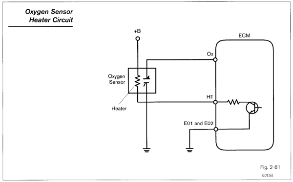
Oxygen Sensor Heater For the oxygen sensor to deliver accurate voltage signals quickly, the sensor needs to be heated. A PTC element inside the oxygen sensor heats up as current passes through it. The ECM turns on the circuit based on engine coolant temperature and engine load (determined from the MAF or MAP sensor signal). This heater circuit uses approximately 2 amperes.
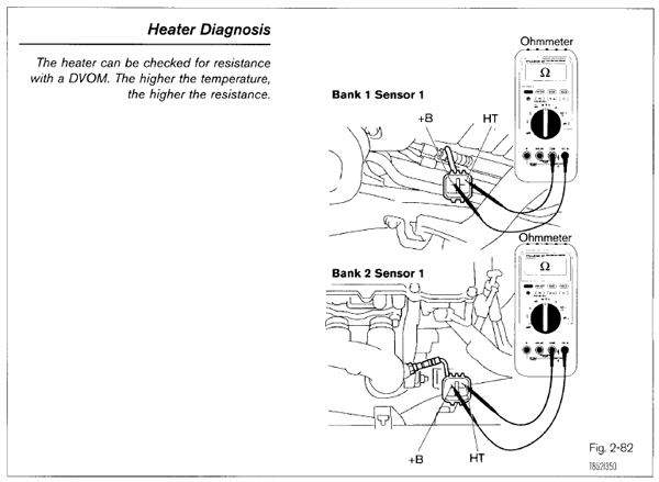
The heater element resistance can be checked with a DVOM. The higher the temperature of the heater, the greater the resistance.
The oxygen sensor heater circuit is monitored by the ECM for proper operation. If a malfunction is detected, the circuit is turned off. When this happens, the oxygen sensor will produce little or no voltage, and possible set DTC P0125.
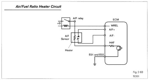
Air/Fuel Ratio Sensor Heater This heater serves the same purpose as the oxygen sensor heater, but there are some very important differences.
Engines using two A/F sensors use a relay, called the A/F Relay, which is turned on simultaneously with the EFI Relay. This heater circuit carries up to 8 amperes (versus 2 amperes for 0, heater) to provide the additional heat needed by the A/F sensor.
This heater circuit is duty ratio controlled pulse width modulator (PMW) circuit. When cold, the duty ratio is high. The circuit is monitored for proper operation. If a malfunction is detected in the circuit, the heater is turned off. When this happens, the A/F sensor will not operate under most conditions and DTC P0125 will set.
Air/Fuel Ratio Sensor Heater Diagnosis
Diagnosis of the heater is a similar to the oxygen sensor. Since the A/F sensor requires more heat, the heater is on for longer periods of time and is usually on under normal driving conditions.
Because the heater circuit carries more current, it is critical that all connections fit properly and have no resistance. The relay is checked in the same manner as other relays.
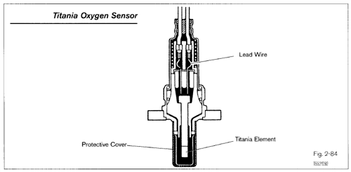
Titania Element Type Oxygen Sensor This oxygen sensor consists of a semiconductor element made of titanium dioxide (TiO2, which is, like ZrO2, a kind of ceramic). This sensor uses a thick film type titania element formed on the front end of a laminated substrate to detect the oxygen concentration in the exhaust gas.
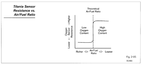
Operation The properties of titania are such that its resistance changes in accordance with the oxygen concentration of the exhaust gas. This resistance changes abruptly at the boundary between a lean and a rich theoretical air/fuel ratio, as shown in the graph. The resistance of titania also changes greatly in response to changes in temperature. A heater is, thus built into the laminated substrate to keep the temperature of the element constant.
OXYGEN / AIR FUEL SENSORS
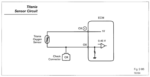
This sensor is connected to the ECM as shown in the following circuit diagram. A 1.0 volt potential is supplied at all times to the 0" positive (+) terminal by the ECM. The ECM has a built- in comparator that compares the voltage drop at the Ox terminal (due to the change in resistance of the titania) to a reference voltage (0.45 volts). If the result shows that the Ox voltage is greater than 0.45 volts (that is, if the oxygen sensor resistance is low), the ECM judges that the air/fuel ratio is rich. If the 0, voltage is lower than 0.45 volts (oxygen sensor resistance high), it judges that the air/fuel ratio is lean.

